Laser Cut Hypotubes (LCHT) are used for many different medical procedures. Most LCHT features consist of small cut or drilled features that allow them to bend and navigate the human body. The inspection for the verification and validation of these small features is an important step in the LCHT’s manufacturing process. As the features shrink in size and become more complex – the inspection also becomes more challenging. Often, these measurements require single digit micrometer resolution. There are multiple ways to achieve this.
acquire high quality surface data
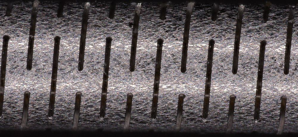
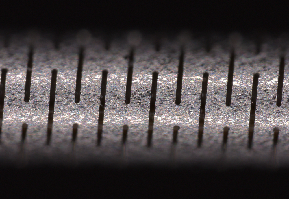
When measuring small features it is necessary to choose equipment with the proper resolution. As a general rule of thumb, your equipment’s resolution needs to be 3-10X greater than the smallest feature you are trying to measure on your part. For example, if you’d like to measure a 30 micrometer feature you will need a measurement resolution of 3-10 micrometer. Resolution in surface metrology relates to how close the pixel spacing is in the final dataset. In the example above, you will want a data point or pixel of data every 3-10 micrometers across the entire feature that you are measuring. The features could be cut patterns like the images below, holes, or defects among other features.
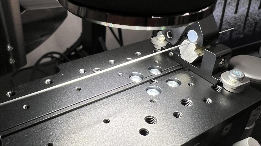
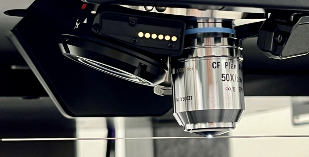
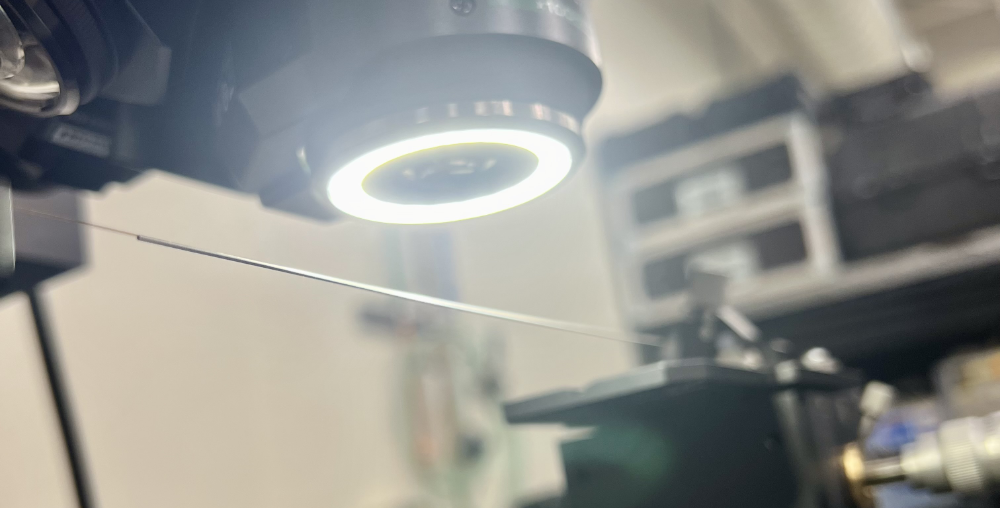
Below: An image of the laser cut hypotube, with the inspection hardware used.
Choose between 2D and 3D data
In general, there are many different measurement technologies available to choose from. Initially you should choose between 2D and 3D data to narrow down the potential options. Measurement systems for 2D are more widely available and prevalent. However, they lack some solutions that 3D measurement systems provide. It is easier to describe why a 3D system may be the best choice instead.
3D Measurement Technologies Help Keep Your Surface in focus
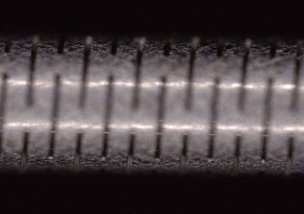
Since LCHTs are cylindrical they are inherently more difficult to measure than flat surfaces. This is because the depth of field of the measurement system must accommodate the tube’s radius. If your measurement resolution requirement is relatively high (i.e. less than 10 microns), it is likely that a 3D system will be needed to see enough of your LCHT’s surface. In the example below, a 3D dataset allows the tube to be in focus. This retains the integrity of the data that will be used for measurement.
3D Measurement Technologies help make certain measurements easier and more reliable
If you need to make measurements on features that don’t have perfectly straight walls, 3D measurement systems become useful. For example, chamfered cuts and holes are difficult to measure with 2D measurement technologies. This is because 2D measurement technologies struggle to determine where the start and stop of a vertical wall or edge exists. The use of a 3D measurement system will make these measurements easier and more reliable.
Below is an example of using a 3D measurement system used to make high quality cut width measurements.
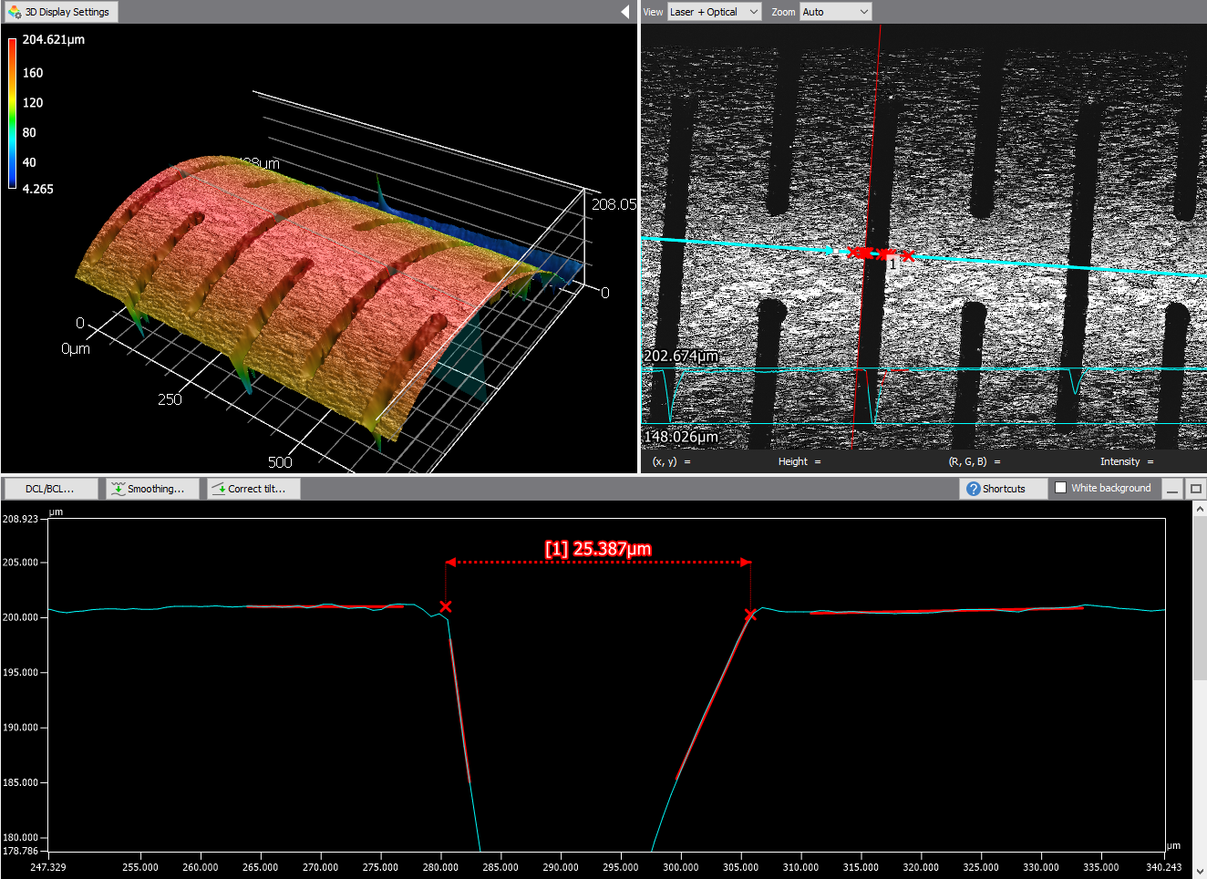
An image showing a 3D laser microscope measuring a section of a laser cut hypotube. The resulting dataset is of a 3D surface. The image above shows the optical 2D image as well as a height profile line drawn across one of the laser cut widths. Because we have 3D data at our fingertips we are able to draw reference lines on the inside of the cut’s walls and the top surface of the tube on either side of the cut. Where these lines intersect is a more accurate measurement of the tube width.
3D Measurement Technologies assist in defect characterization
Two dimensional (2D) measurement systems are good at locating potential defects on the surface of your tube. However, it is hard to decipher what the defect is from the image alone. Often, it is even unclear if the image is recessed into the surface (e.g. a dent) or a protrusion (e.g. debris or burr). The example below shows how 3D data can be used to interrogate an anomaly on the tube’s surface.
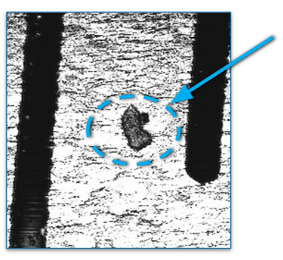
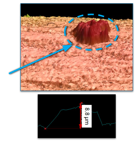
Left: An image showing a 2D optical image of the surface of the tube. Right: Using the 3D data to see the surface of the tube at an angle. This helps us determine that this defect is a protrusion. We can then measure the protrusion to determine if it is within specification or not. This defect was measured to be 8.8 micrometers tall.
Selecting the right measurement technology for your process
There are an overwhelming amount of options to choose between. So what’s the right measurement technology for you? Focusing on micrometer-size resolutions, it is clear to us that a 3D measurement technology is the best route given the reasons described earlier. Beyond this, the total measuring time per tube and the available analysis software options lead us to a few good options.
Confocal microscopes offer excellent 3D data quality and flexibility. Their high resolution and large depth of field ranges are ideal for measuring tubes with the highest quality. However, they are slow at taking data if you are trying to capture information across the entire tube’s surface. An individual measurement over a few hundred micrometers of tube surface will take 30 seconds or more. This means that this technology is not realistic for 100% inspection in a production setting.
Digital imaging equipment is ideal for faster areal measurements. Each image can be taken in a fraction of a second, but depth stacking multiple layers of images may take a few seconds. However, they are still faster than confocal microscopes and are a good alternative when high resolution 3D data isn’t the primary use case of the equipment.
Confocal 3D sensors offer fast data acquisition rates that allow you to scan the entire tube surface. Since the data comes back as raw height information it is important to understand how to analyze such data. It is not as straightforward as a microscope with pre-existing software for analysis. But given the right boundary conditions, highly repeatable measurements can be made quickly. These types of sensors require a highly precise motorized motion system as well. We work with Aerotech motion control products to ensure the measurement data quality is retained while continuously scanning.
Putting it all together
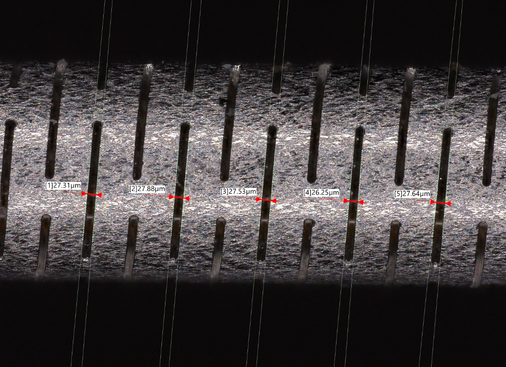
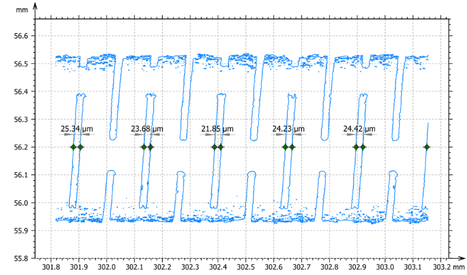
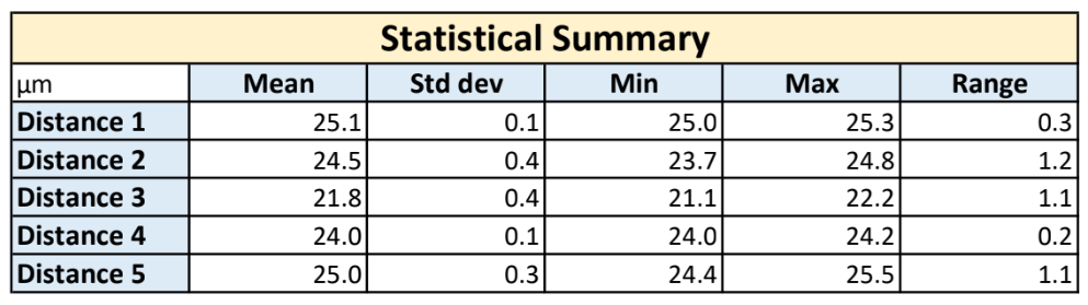
Measuring LCHTs is an ongoing challenge. Their feature size is shrinking and the complexity of the features is increasing. Therefore, thought needs to be put into selecting the right measurement technology for your project. First, decide between a 2D or 3D measurement technology early on. Then choose the right type of device for your project. For example, below we used a confocal measurement technology to measure 5 cut widths along a hypotube. This can be scaled up to cover the entire length of the tube.
For more guidance and consultation please reach out to us. We offer full engineering and laboratory testing services to help guide our customers towards the right solution to their measurement challenge.